SamSuka
bigclive
bigclive

patreon


Overvoltage and undervoltage detector

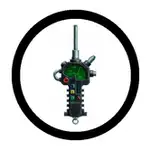
This isn't what I thought it was:-

https://youtu.be/NX84d45ZlBM

And the circuitry wasn't what I thought it was going to be either.
It was almost harder to reverse engineer because of its simplicity.

Overvoltage and undervoltage detector

Comments

The mains voltage can vary quite dramatically.

Big Clive

If I got my sums right those thresholds would roughly be +/- 20% of the mains voltage. Is that normal?

Raven Luni

Thanks.

Big Clive

Looks good. Nice bright garage.

Big Clive

You can get mains to opto-isolator modules on eBay for detecting mains presence. This could indicate a voltage anomaly though.

Big Clive

That looks like it would be a nice little circuit to adapt for use with an optocoupler for an AC_FAIL micro input.

neal richard

I have to say the Saturday Live streams have become a staple of my Saturday evening entertainment. I've fitted a 50" TV to the wall of the garage so I can watch the stream while tinkering at my old Japanese cars. A little picture of the setup in action: https://ibb.co/cD7R4Hn

Mark Chapman

Happy Birthday Big Clive! :)

David Glover-Aoki

Yes. Perhaps that's why it's outside the bridge - to take advantage of inductance?

Mike Page

I'm very curious what would happen to that small coil if the power wasn't cut properly... Might be an interesting follow-up video? For dramatic effects, so to say.

Paul Schuur

They needn't bother with the language. Colourful enough!

Ymir the Frost Giant

very nice, it is uprising just how small and simple the cur cit was.

DC Allan

My Variac is in need of attention. It's weight was not in its favour during travel. I'd probably use a tungsten lamp in place of the coil for the tests.

Big Clive

The crowbar approach is also used on many simple RCDs/GFCIs to allow a decisive trip without needing a bulky power supply to handle the current of a low voltage coil.

Big Clive

Very nice - a bipolar crowbar! And very neatly laid out on a single-sided board. I imagine getting it to start up gracefully needed a bit of tuning. If you have an overwound variac kicking about it would be nice to measure the high/low limits. Might have to avoid smoking the coil though.

Mike Page

No electrolytic capacitors either, so a properly flow soldered PCB would be under low stress. The resistors are all suitably rated for the voltage too - even the brief overvoltages.

Big Clive

A great video again! Quite clever how they did that. Also looks pretty reliable. The solenoid in series with the circuit. The circuit uses a crowbar method to activate the solenoid. Simple but effective.

Frank

I see that very clearly. Nice!

Michael Thompson

Clive I really appreciated the coloured bits of the schematic.

Nuts 'n' Proud

From the tongue in cheek department... Into music "Police Squad" theme and a announcer says "Big Clive Dot Com IN COLOR!"

Nuts 'n' Proud

So clever yet simple - great to see

RDM

When the operation noise goes from "click" to "CLIK-KLUNK" :-)

Mr B Shepherd

Stupid question. At what rating does a relay become a contactor?

Dr Andy Hill

The basis of your circuit reminded me of a super simple single resistor key lock. Where if the resistor key was too high or too low it would trip a relay 'lockout', a built-in timer would also prevent anyone using a variable resistor. Absolutely brilliant!

Andrew Donaldson

Oh this was neat! I have always enjoyed journeys into breakers and relays and contactors. That is speaking as someone who gets to see them after they have blown up inside a piece of industrial gear. As I mentioned in my YouTube comment I thought the colorization of the schematic proved to be quite helpful. So much so that the Turner Broadcasting Company has expressed interest in colorizing all of your classic videos! Wow! :D

Michael Thompson

I'm thinking because the high and low are "tuned" with resistors, this thing would be fairly robust over time? Maybe the coil would fail after a large number of trips?

Wim

What an awesome thing to wake up to! Thanks Clive! - and hey thanks again for the live streams. Much fun and frivolity.

Michael Thompson

When I saw your own schematic with the 3 resistor voltage divider I immediately thought there must be a 555 in there. I guess I was wrong.

Zeedijk Mike

The wonky readings were caused by the meter's low test voltage and the number of diode junctions.

Big Clive

It was a very early RGB controller that did all the colour processing and pulse width modulation in software. It was a bit ahead of its time, so people tried many ways to get me to part with the assembly code. I still sell the chips and controller kits, but not right now due to Covid and politics.

Big Clive

Could you apply R=1/(2πfC) here and predict that it would not be a capacitive dropper? Plugging in the numbers gives C≈570pF, which sounds way too small.

Michael Dunn

In one of your live streams you was talking about how you used to sell something that had software on it and people would try and trick you into giving them the software/code, I would love a video going more in-depth to what you was selling and some of the stories people gave you

Very Interesting.

Basti Elektronik


More Creators